Tube0D
Module summary
Tube0D is designed to simulate pressure-volume relations of vessels.
Parameters
- l [m]: double
Length of the tube
- A_wall [m 2]: double
Cross-sectional area of the wall
- k [-]: double
Stiffness coefficient of the wall
- p0 [Pa]: double
Pressure at A=A0
- A0 [m 2]: double
Cross-sectional cavity area for p=p0
- target_wall_stress: double
Adaptation target for wall stress
- target_mean_flow: double
Adaptation target for mean flow
Signals
- V [m 3]: array
Volume in the Cavity
- p [Pa]: array
Pressure in the Node
Physiological background
The blood circulation consists of a pump (the heart), conduits (larger blood vessels) and the microvascular beds of tissues and organs, that requires transport of nutrients to and waste products from them. The ArtVen module is designed to represent the hemodynamic load for a given vascular bed, either consisting of a confined section of tissue (e.g. skeletal muscle) or an organ (e.g. kidney or brain), or for an entire pulmonary or systemic vascular bed (spanning from valve to atrium). Such a given vascular bed is a branching network structure from the large feeding and draining vessels inwards (Fig. 6 ). Typically, blood enters via larger arteries, passes a microvascular part with the smallest vessels, and is drained by larger veins.
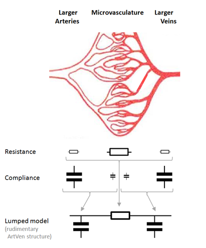
Fig. 6 Anatomical structure of a vascular bed and associated hemodynamic properties. The larger vessels at the arterial and venous sides contribute the most to the compliance of the bed, while the microvasculature contributes is the prime determinant of the relationship between flow through the bed and pressure difference across it. Because of these distributions the properties of a vascular bed can be represented by a lumped model.
Model Description
The Tube0D module is a Cavity for which the transmural pressure and wave impedance are described as function of the normalized cross-sectional area \(A_{norm}\) of a cylinder with length \(l\) and cavity volume \(V(t)\).
To do so, we use a normalized area \(A_{norm}\) based on the state variable \(V\)
Transmural pressure \(p_{\text{trans}}\) is calculated based on reference pressure \(p_0\), reference area \(A_0\), and a nonlinear scaling factor \(k\):
Wave impedance \(Z\) in a cylindrical tube is the ratio of pressure \(p\) to flow \(q\), expressed as a function of blood density \(\rho_b\), pulse wave velocity \(c\), and cross-sectional area \(A\):
Pulse wave velocity \(c\) is given by:
The pressure-volume derivative \(\frac{dp}{dV}\) is derived from the transmural pressure to volume relationship:
with
and
Therefore, the pressure-volume derivative of a Tube0D element is
The pulse wave velocity \(c\) (Equation 4) in the Tube0D then is
Filling Equation 9 into Equation 3, we find the wave impedance \(Z\) for the Tube0D element:
The Tube0D inherets all properties form the Cavity.
Therefore, the pressure inside a Tube0D element is calculated based on the transmural pressure \(p_{trans}\), the external pressure of the surrounding cavity \(p_{extern}\) (optional, \(p_{extern}=0\) in absence of a surrounding cavity), wave impedance \(Z\), and netto flow of the tube \(q\):
Numerical Implementation
No additional assumptions are made on top of the equations shown above.
The verification of this module can be found here
Sensitivity Analysis
(Source code, png, hires.png, pdf)
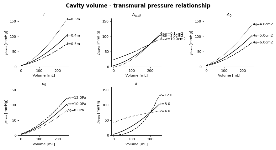
Fig. 7 Black line shows a typical relationship between Cavity volume and transmural pressure. Dotted and dashed lines represent a change in a single parameter with respect to the typical relationship. More information on how to read the Sensitivity Analysis here.
|
Tube0D is designed to simulate pressure-volume relations of vessels. |